
Injection Mold Basics
Undercuts and Side Actions
UNDERCUTS
Undercuts are those portions of the part that can not be pulled in the line of draw. If an undercut were to be machined into a mold without a mechanism to releive it, the part would be destroyed upon mold opening or ejection.
Undercuts can usually be divided into two categories, internal and external.
As a general rule SLIDES are used to pull external undercuts and LIFTERS to pull internal undercuts.
There are many different types and styles of slides and lifters. Every tool shop seems to have "the only way that it can be done" and no two do it the same. Go figure. If the mechanism is durable and molds good parts then it is a good one. Place your trust in mold shops who have to service and repair their own molds on their own dime on this one.
This is another area where standardization is being attempted by several companies. The broad range of demands made by widely varying plastic parts makes this a difficult item to standardize however. I like the modular slides made by Omni.
SLIDES
Slides are usually used for relieving external undercuts or to allow for zero degree draft on part exteriors. Their motion can be driven by one of several mechanisms. Any slide mechanism must also employ a locking device to hold the slide against the ravages of molding pressures in excess of 10,000 psi.
Slides may generally be categorized by their driving mechanisms.
Cam Pin Slide
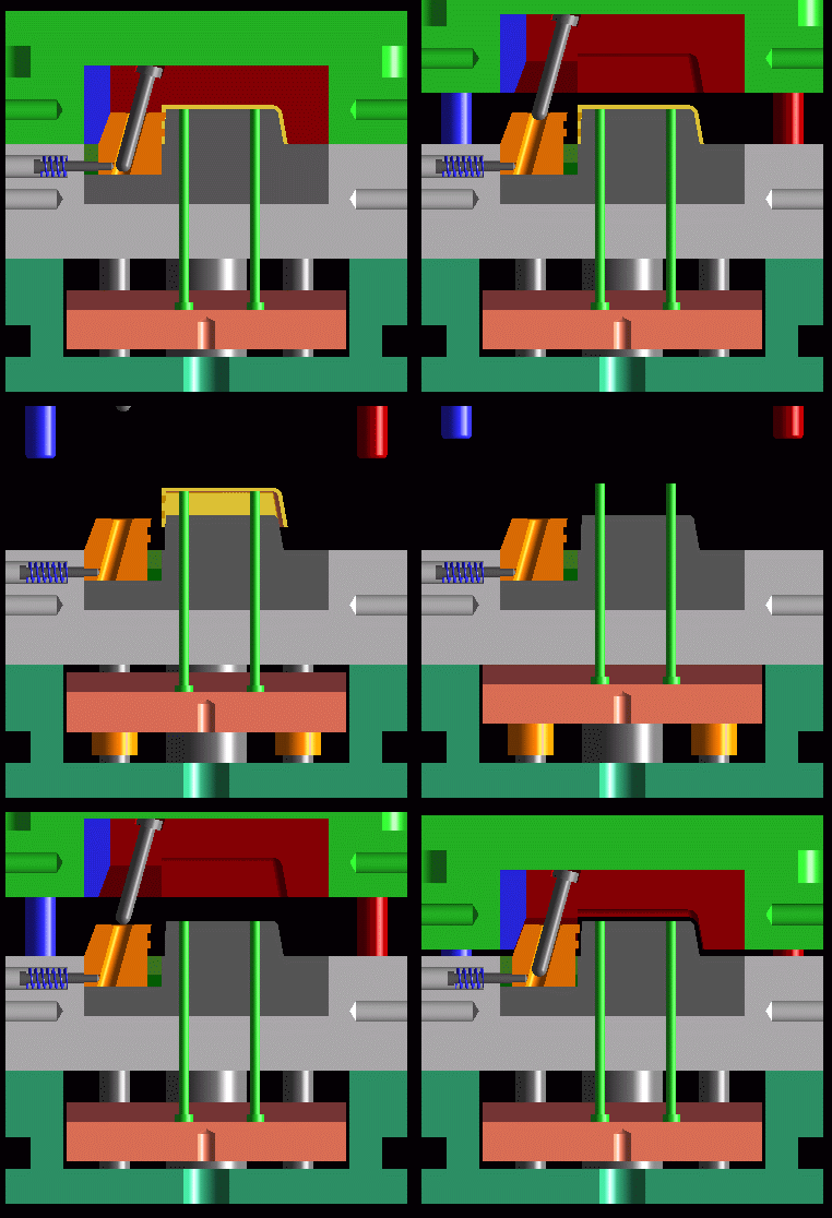
Known as a cam pin, angle pin, horn pin, etc., this is the most common and versatile of all slide mechanisms. It is driven by the opening of the press. The action of the angled pin withdrawing from the angled hole drives the slide back. Springs hold the slide in the retracted position. Upon press closing the cam pin returns to drive the waiting slide back almost to molding position. Finally then the lock seats against the back of the slide, driving it to its home position and clamping it there for the duration of the next shot.
Cam Slide
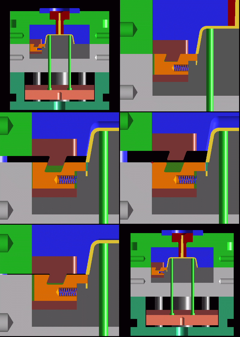
Similar to the cam pin slide in principle, the cam actuated slide is limited to strokes of about 0.080 in. The cam slide is good for relieving very small localized undercuts such as one word of raised text on the side of a product or a few small holes. Instead of using a pin it simply has a metal cam that also incorporates a lock.
Hydraulic slide
Hydraulic slides are frequently used when pecker pins won't work for some reason. For example very tall slides must be pulled hydraulically because pecker pins exert too much torque on the slide gibs and may cause binding. Locks are still incorporated in the same manner as in a pecker pin slide. Shown is an example of hydraulic slides as used in the Silicon Graphics O2 top case tool.
Locking hydraulic slide
Locking hydraulic cylinders are used when undercuts occur in the cavity side of the tool. This is a situation that the savvy part designer will avoid if at all possible. Locking cylinders have a self contained locking mechanism that helps the cylinder hold against molding pressure. They are rated by pounds of holding pressure. This is calculated by multiplying the projected molding area on the slide by 10,000 psi.
Spring actuated slide
Spring slides are usually not a good idea for plastic injection molds. Perhaps the only exception would be for shallow molded text. The problem with spring actuation alone is that it is not positive. If the grip of the molded plastic can overcome the compressive strength of the spring then the slide will not retract. When the ejection comes forward, ugly things will happen. Spring slides work well however with investment casting wax.
Delayed action
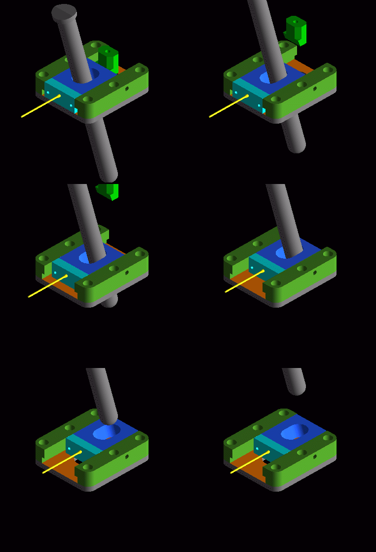
Any of these slide mechanisms may have a delay built in. The designer may thus sequence the order of slide pulls if necessary, or may cause a slide to wait until some other action in the tool is done before activating. Delay on mechanical slides is accomplished by simply leaving an air gap behind the pecker pin or cam. Then as the mold opens the slide does not move until the cam crosses the air gap and begins to push upon the slide.
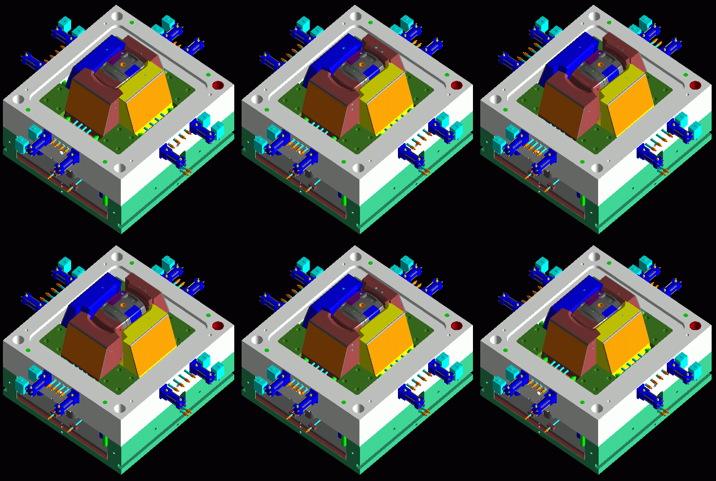
Hydraulic slide
Hydraulic slides are frequently used when pecker pins won't work for some reason. For example very tall slides must be pulled hydraulically because pecker pins exert too much torque on the slide gibs and may cause binding. Locks are still incorporated in the same manner as in a pecker pin slide. Limit switches tell the press whether the slides are in or out. This is a big file but cool to watch.
Shown is an example of hydraulic slides as used in the Silicon Graphics O2 top case tool.
Cam Pin Slide
Known as a cam pin, angle pin, horn pin, etc., this is the most common and versatile of all slide mechanisms. It is driven by the opening of the press. The action of the angled pin withdrawing from the angled hole drives the slide back. Springs hold the slide in the retracted position. Upon press closing the cam pin returns to drive the waiting slide back almost to molding position. Finally then the lock seats against the back of the slide, driving it to its home position and clamping it there for the duration of the next shot.
Cam Slide
Similar to the pecker pin slide in principle, the cam actuated slide is limited to strokes of about 0.080 in. The cam slide is good for relieving very small localized undercuts such as one word of raised text on the side of a product or a few small holes. Instead of using a pin it simply has a metal cam that also incorporates a lock.
Locking Hydraulic Slides
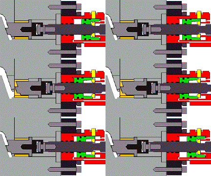
2 - D
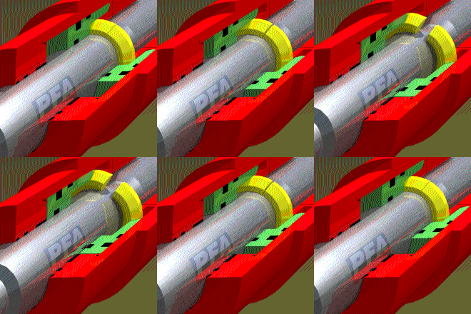
3 - D
KOR-LOK locking hydraulic slide by PFA
Locking hydraulic cylinders are used when undercuts occur in the cavity side of the tool. This is a situation that the savvy part designer will avoid if at all possible. Locking cylinders have a self contained locking mechanism that helps the cylinder hold against molding pressure. They are rated by pounds of holding pressure. This is calculated by multiplying the projected molding area on the slide by 10,000 psi. If you must have cavity side undercuts that require a locking cylinder, specify KOR-LOK by PFA ( www.pfa-inc.com ). They are the most compact and dependable locking cylinders available. PFA is also capable of locking against greater forces than other cylinders available.
Does your part have cavityside undercuts? Can they be designed out? Don't know? e-mail: kevin@paralleldesign.com
Delayed action
Any of these slide mechanisms may have a delay built in. The designer may thus sequence the order of slide pulls if necessary, or may cause a slide to wait until some other action in the tool is done before activating. Delay on mechanical slides is accomplished by simply leaving an air gap behind the pecker pin or cam. Then as the mold opens the slide does not move until the cam crosses the air gap and begins to push upon the slide. In hydraulic slides delay is accomplished electronically by the molding machines computer.
LIFTERS
Lifters are used primarily for relieving internal undercuts or for zero draft internal faces. Their motion is driven by the molding press pushing on the ejector plates. simple side action lifter withdraws at 90 degrees to the line of draw , simultaneous with ejection. The angle of the lifter passing through the core frequently confuses the novice into thinking that it pulls the feature at an angle. Relative to the core the lifter indeed moves at an angle. Relative to the part however a lifter moves directly sideways because the part is being ejected forward at the same rate as the lifter.
Having said all that however, it possible to run a lifter at a small angle to the part, but this requires special hardware. These variants will be discussed later.
DESIGN CONSIDERATIONS
- Draft must be altered in the locale of the lifter. The lifter will be pulling sideways so draft in this area must be oriented in the lifters line of draw.
Features such as ribs and bosses must not be placed in the way of lifter motion. Depending upon the size of your lifted feature you must allow for three things, the lifter body, lifter stroke, and 0.050" wiggle room to the next feature. These three requirements really depend upon many factors including the overall size of your part, the depth of undercut to be pulled, shape of the feature that you are pulling and the style of lifter used. As a rule of thumb however, if you are just pulling a typical hook or snap, leave 1.250" of room for lifter body, stroke, and clearance.
Variants include:
Accelerated lifters
Similar to conventional lifter but moves at an upward angle relative to the part. Feature angle limit is 10 degrees. Determine the angle at which your lifter must travel and draft the feature relative to that vector.
Retarded lifters
Similar to conventional lifter but moves at a downward angle relative to the part. Feature angle limit is 10 degrees.Determine the angle at which your lifter must travel and draft the feature relative to that vector.
Straight up lifters
Track straight up with the part just like an ejector pin. The press operator must then pull the part off by hand. Best when used on simple features. Use liberal draft. Operator must be able to release the part by shifting it in one direction only. Risks include human damage to the part, and slower, irregular cycle times.
Cam lifters
Very limited in depth of undercut and location. Good for small spaces however. Some durability issues. Recommended as a last resort only.
Drag along lifter
-El Cheapo. O.K. for prototype tools or those built in third world countries. Requires that the cavity side return it to its home position.
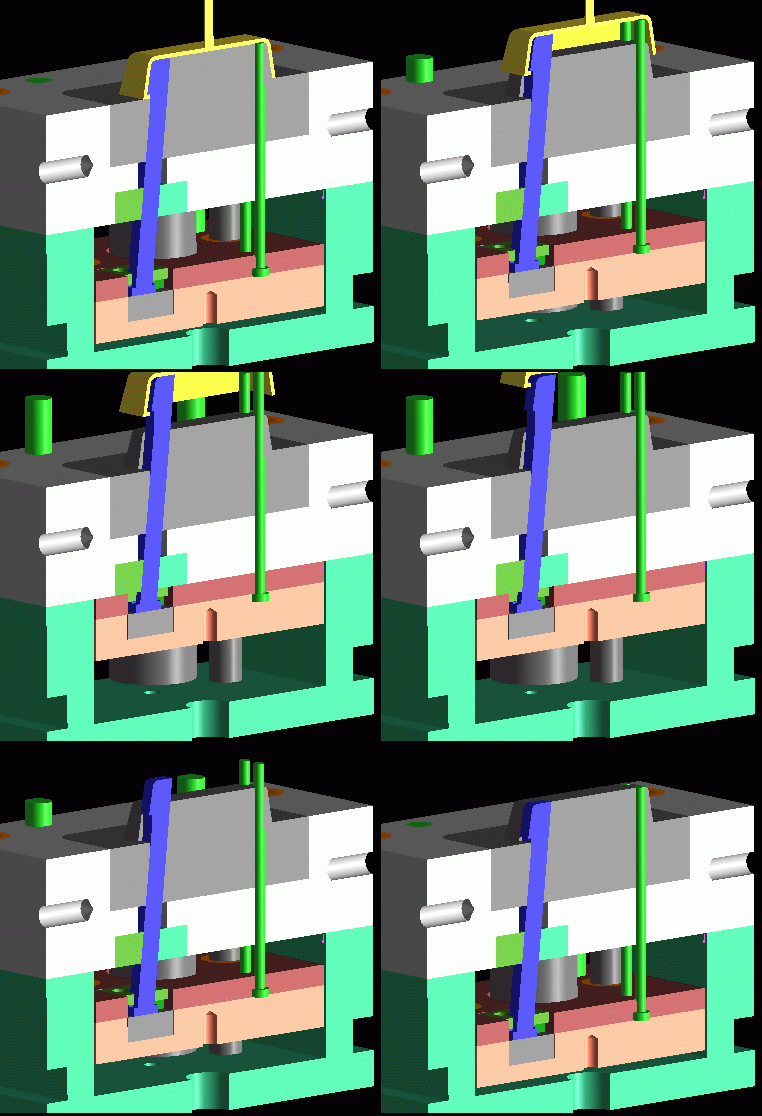
SIMPLE LIFTER
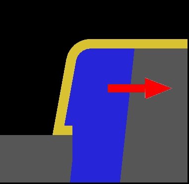
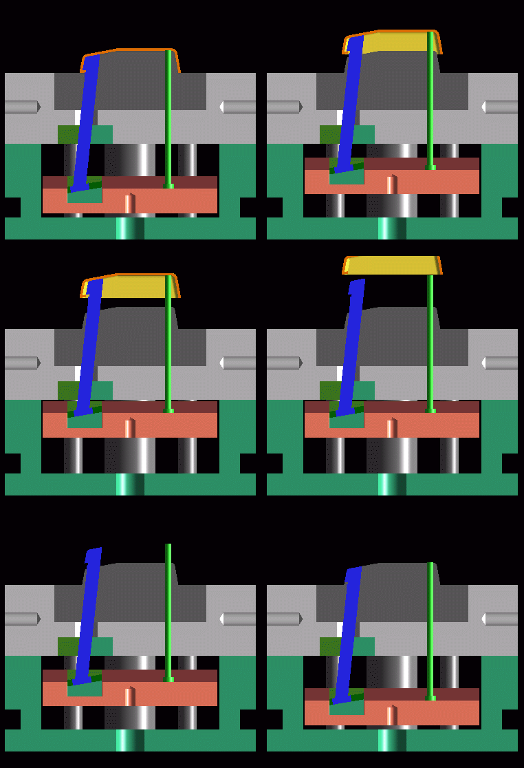
Lifters are used primarily for relieving internal undercuts or for zero draft internal faces. Their motion is driven by the molding press pushing on the ejector plates. simple lifter withdraws at 90 degrees to the line of draw , simultaneous with ejection. The angle of the lifter passing through the core frequently confuses the novice into thinking that it pulls the feature at an angle. Relative to the core the lifter indeed moves at an angle. Relative to the part however a lifter moves directly sideways because the part is being ejected forward at the same rate as the lifter. Note also that the lifter moves at 90 degrees relative to the ejector plates as the lifter foot slides along its gib.
ROOM 2 MOVE
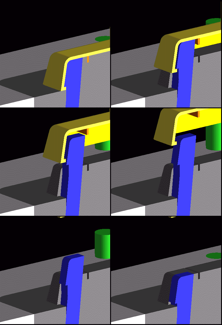
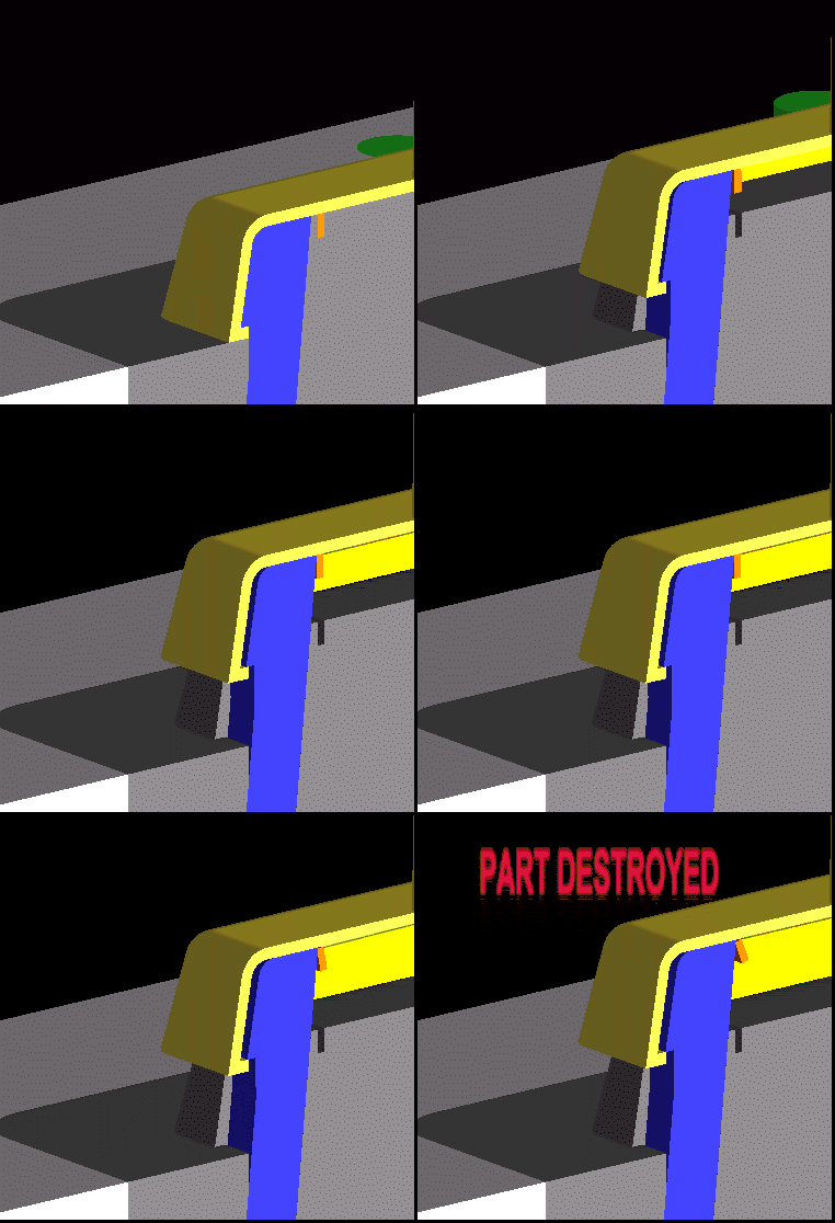
Features such as ribs and bosses must not be placed in the way of lifter motion. Depending upon the size of your lifted feature you must allow for three things, the lifter body, lifter stroke, and 0.050" wiggle room to the next feature. These three requirements really depend upon many factors including the overall size of your part, the depth of undercut to be pulled, shape of the feature that you are pulling and the style of lifter used. As a rule of thumb however, if you are just pulling a typical hook or snap, leave 1.250" of room for lifter body, stroke, and clearance.
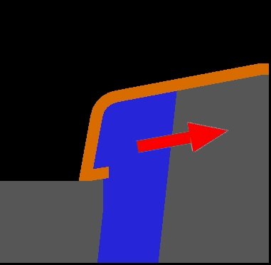
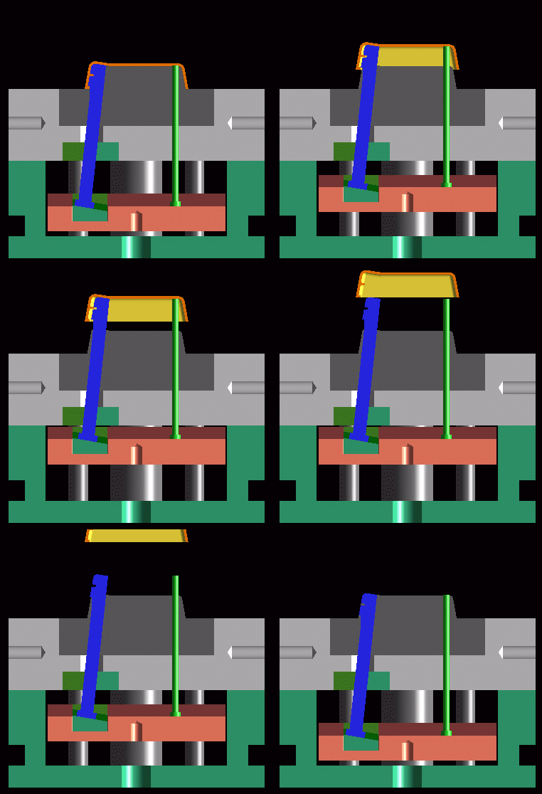
Accelerated lifters
Similar to conventional lifter but moves at an upward angle relative to the part. Feature angle limit is 10 degrees. Determine the angle at which your lifter must travel and draft the feature relative to that vector.
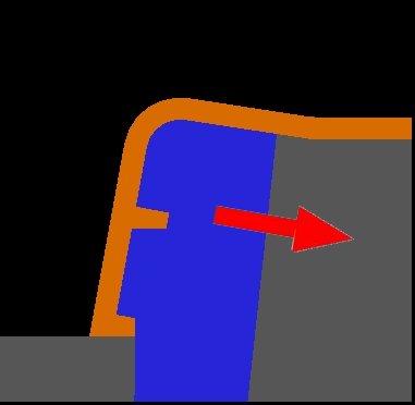
Retarded Lifter
Similar to conventional lifter but moves at a downward angle relative to the part. Feature angle limit is 10 degrees.Determine the angle at which your lifter must travel and draft the feature relative to that vector.
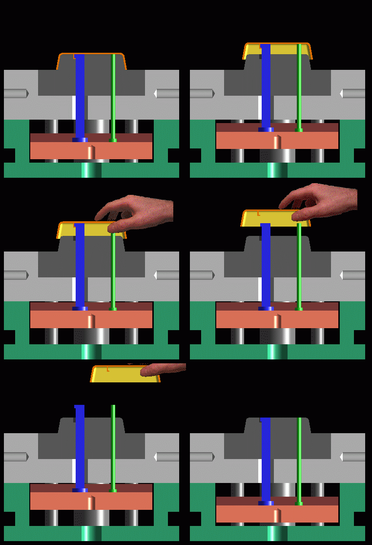
Straight up lifter
Track straight up with the part just like an ejector pin. The press operator must then pull the part off by hand. Best when used on simple features. Use liberal draft. Operator must be able to release the part by shifting it in one direction only. Risks include human damage to the part, and slower, irregular cycle times.